Bend Sensor |
You will need:
- velostat bags
- Adhesive copper tape (with conductive adhesive)
- PVC paper
- Insulation tape
- Spray mount, multimeter, 1k resistor, scissors, ruler.
|
This sensor is very similar in design to the low profile force sensor that employs the semiconductive properties of velostat bags used to protect components against static (fig. 1). Principally the dimensions are altered and there are subtle design changes. As a reference, the velostat I have used in this example has a resistance of approximately 20 kilo-ohms diagonally from corner to corner of a 25mm square. |
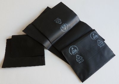 fig. 1
|
|
The two conductors, made from copper tape, will conduct increasingly through a strip of velostat as the sensor is bent. This is because bending the sensor will result in a greater area of the upper copper strip (see fig. 2) coming into contact with the velostat strip and with greater pressure, both actions resulting in lower electrical resistance from copper strip to copper strip. The air gap, creating using a narrow lip of insulation tape, ensures separation of the conductors and therefore maximum resistance when the sensor in unbent. |
 fig. 2
|
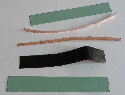 fig. 3
|
Fig. 3 shows the various components that will comprise the bend sensor. The two plastic strips are 100mm by 15mm and the velostat strip is slightly smaller, about 97mm by 12mm. The copper strips are slightly longer than the plastic strips so that tabs to which connections can be made, will be formed outside of the sensor. The copper strips are about 5mm in width. You could use wider copper strips if you like but they may then dampen the springiness of the sensor to return to being straight when released. |
|
Stick one of the copper strips onto the velostat strip using the adhesive side of the tape and then glue this onto one of the plastic strips using spray mount and copper side down. Take care not to get any glue on the exposed velostat side as this will compromise conductivity. Ensure the velostat lies flat on the plastic strip with no wrinkles. Fold the overhanging adhesive copper tape onto itself to create a tab to which connections can be made. |
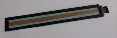 fig. 4
|
Stick the other copper strip directly onto the other plastic strip, again creating a tab for connections, and create a shallow lip around the edge of the plastic strip using insulation tape. A small piece of insulation tape on the underside of the copper tab will prevent short circuits between the two tabs when the sensor is put together. |
|
Bind the whole sensor together using insulation tape or craft glue (again taking care to only get glue on the insulation tape 'lip' and not on the copper or velostat strip). Using glue will give a more solid sensor but if you use insulation tape you will still be able to dismantle the sensor if something needs adjusted. |
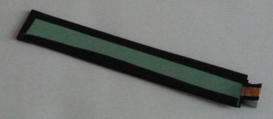 fig. 5
|
|
In the demonstration movie opposite the sensor is used to control the cutoff of a resonant lowpass filter being applied to a sawtooth wave. When compared to a commercial bend sensor (2nd half of the video) it becomes apparent that the home-made version covers a wider range than the bought one and also that the bought sensor does not default to a minimum value. The bought sensor is only useful in one direction - the home-made version can be bent in both directions to produce similar sensing results. A sensor with reduced sensitivity can be made by inserting another velostat strip between the upper copper strip and the air gap (see fig. 2). The copper strip should then be flipped around and stuck to the velostat using its own adhesive side as was done with the lower copper/velostat layer. |
|
The dimensions of the sensor can be experimented with. Bear in mind that the springiness of the sensor is dependent upon the width. Sensors can be tailored to particular applications. In the video opposite a shorter, narrower bend sensor is used to track the bending of a finger. |