Force Sensor (FSR)- using conductive foam |
You will need:
- Semi conductive foam
- Adhesive copper tape
- PVC paper
- Insulation tape
- Gaffer tape
- Multimeter, 1k resistor, scissors, ruler.
|
This sensor acts as a force sensitive resistor (FSR) and is used to sense physical force. It makes use of high density conductive foam* (fig. 1), a material that is frequently used as anti static protection in the packaging of static sensitive electronic components. It comes in sheets of size A4 or larger and with a thickness of around 5mm. This sensor has a slightly higher profile than my other design for an FSR that uses anti static neoprene sheeting, but might be more useful in a situation where a greater force feedback is beneficial when force is applied. *Low density foam has a much higher resistance and will not work here unless the sensor is extremely large. |
 fig. 1
|
|
This foam conducts electricity, but not very well so it can be considered a resistor - or a semiconductor.
When the foam is at rest it is full of air bubbles and air is a very good electrical insulator.
If the foam is compressed,
more of it comes into contact with itself with the consequence that it then conducts a bit better (and resistance reduces).
It is this behaviour which allows us to use it to sense force.
We will create a kind of 'resistor' sandwich with a conductor (copper tape) either side of the foam. |
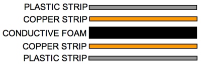 fig. 2
|
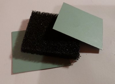 fig. 3
|
Cut a piece of conductive foam - in the example I have cut a piece 35mm x 35mm but by all means experiment with different shapes and sizes. Bear in mind that as the size of the piece of foam is increased the resistivity across the bit of foam is reduced. If the resistivity of the piece of foam is reduced too much then the resistance of the sensor in its resting state may not register as zero. For very large sensors a double layer of foam will raise the resistance back to a level where at rest the sensor registers zero or alternatively you could experiment with low density conductive foam. If you use a much smaller piece of foam the sensor my be less sensitive. Cut two pieces of plastic paper, just slightly smaller than the piece of foam. These are optional but they will help to strengthen and to keep the two conductors flat. |
|
Stick a layer of copper tape to one side of each piece of plastic paper. Add another narrow piece of copper tape perpendicular to the ones already attached. Make it a bit longer so that it extends off the sensor. Fold this portion of the copper strip that overhangs over onto itself (on the adhesive side) so that it sticks to itself and forms a tab that we can attach a crocodile clip to or solder a wire to. A short collar of insulation tape will prevent the possibility of a short circuit if the two tabs touch when pressure is being applied (see fig. 4) |
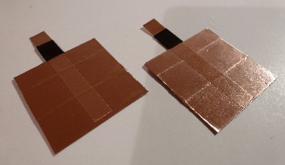 fig. 4
|
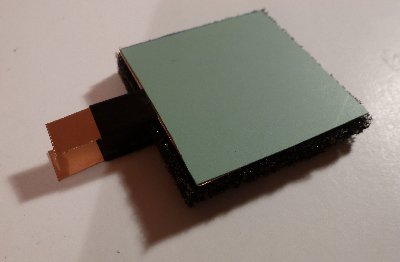 fig. 5
|
The two conductors will be placed on top of and underneath the foam so that the copper side is in contact with the foam (fig. 5). |
|
Encase the entire sandwich in gaffer tape so it won't fall apart (fig. 6). Take care to completely cover the conductor and foam (apart from the end of the tabs) but don't overlap gaffer tape excessively. this might require a bit of care. |
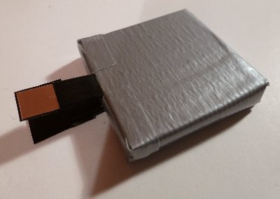 fig. 6
|
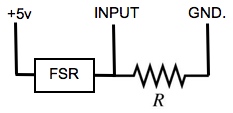 fig. 7
|
Connect one of the tabs of the sensor to an analog input of your Arduino (or equivalent) and the other to +5v. Connect a resistor between the same analog input and ground (see fig. 7). Typically this resistor should be around 10 k.ohms but it might be worth experimenting with resistors between 1k and about 25k. Using a lower value resistor might make the sensor more sensitive, too low a resistor and the sensor will not output zero when at rest. |
|
In the demonstration movie opposite the sensor is used to control the cutoff of a resonant lowpass filter being applied to a sawtooth wave. |