This sensor acts as a force sensitive resistor (FSR) and is used to sense physical force.
It makes use of material (velostat) from the type of black bags that are used to store and protect static sensitive electronic components (fig. 1).
You may already have one of these if you have ordered electronic components online but if you don't, you can order them separately.
The material these bags use conducts electricity but not very well so it can be considered an electrically resistive material or a semiconductive material.
The velostat I am using in this example has a resistance of approximately 20 kilo-ohms from corner to corner diagonally for a 30mm square.
This sensor has a lower profile than my other design for an FSR that uses conductive foam. In some cases it may be more sensitive.
fig. 1
The sensor will comprise of a piece of the velostat and a similarly sized conductor (copper tape) separated by a thin air gap.
As the sensor is pressed the conductor will make contact with the velostat. As pressure is added
(the assumed situation is that a finger or thumb is pressing the sensor) more of the conductor makes contact with the velostat
and that contact becomes better as they are pressed together thereby reducing the electrical resistance between the two.
It is this behaviour that allows us to sense the amount of force applied to the sensor.
fig. 2
fig. 3
Cut two pieces of acetate/plastic/PVC paper which will form the upper and lower surface of the sensor.
In this example the pieces I have cut are 35 x 35mm. This represents a good size for fingertip pressure.
Cut a piece of velostat, slightly smaller than the pieces of plastic paper you have just cut.
Cut two pieces of copper tape the same size as the velostat square.
If your copper tape is narrower than required just cut several pieces that will cover the same area.
Finally cut two strips of copper tape that are a couple of centimetres longer than the acetate squares,
these will be used as connection tabs for the sensor.
Stick one of the copper tape squares (in this example aluminium tape was used) in the middle of one of the acetate squares.
It is essential that the adhesive on the tape is conductive, check this beforehand with a multimeter if you are not sure.
Attach one of the narrow copper strips to the copper/aluminium square and fold it over onto itself (sticky side on the inside) to form a sturdy tab to which connections,
either soldered or using crocodile clips, can be made.
fig. 4
Stick the other copper/aluminium square on one side of the velostat square.
Attach the other copper strip to the copper/aluminium square side and fold it over onto itself (sticky side on the inside) to form the other connection tab .
fig. 5
fig. 6
Attach the velostat covered conductor to the centre of the other piece of plastic using spray mount.
Take care not to get any spray mount on any of the exposed velostat.
Build up a small lip around the edge of the velostat square using narrow strips of insualtion tape.
A single layer of insulation tape should suffice.
The insulation tape 'lip' should overlap both the exposed border of acetate and a little of the exposed velostat.
This thin spacer will be required to maintain an air gap between the exposed conductor and the velostat covered conductor when the sensor is not being pressed.
fig. 7
(finished sensor picture)
fig. 8
Bind the two sides of the sensor together using insulation tape or glue.
Take care that the two contacts won't short circuit.
Connect a resistor between the same analog input and ground (see fig. 9).
Experiment with resistors in the range 1k to 25k to find out which gives best results.
fig. 9
In the demonstration movie opposite the sensor is used to control the cutoff of a resonant lowpass filter being applied to a sawtooth wave.
The sensor should be fairly sensitive to light touch but it should not reach maximum too easily.
The home-made FSR should compare favourably, and even out-perform in some respects, a commerially available FSR.
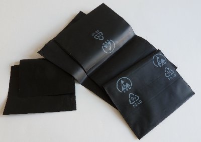 fig. 1
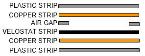 fig. 2
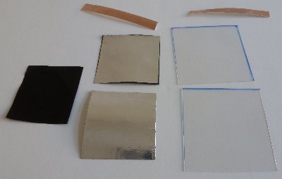 fig. 3
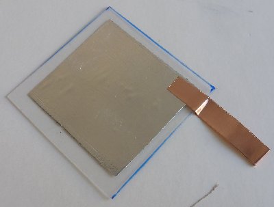 fig. 4
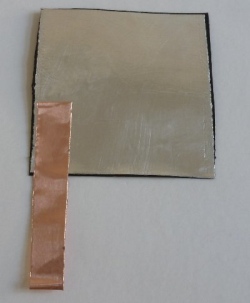 fig. 5
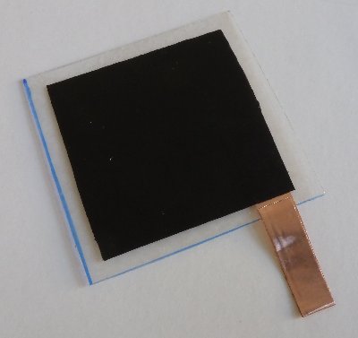 fig. 6
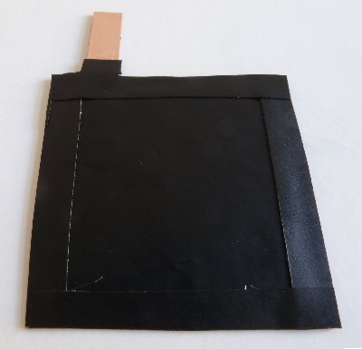 fig. 7
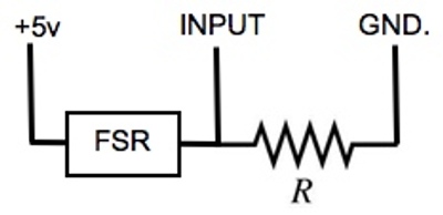 fig. 9