|
Hacking a Gamepad for use as a Controller Interface
|
USB gamepads belong to a class of devices referred to as HIDs (human interface devices).
This group of devices also includes things like USB mice, keyboards and drawing tablets.
This definition of a class allows these devices to be connected to computers with a minimum of fuss and more often that not specific device drivers will not need to be installed
- this feature is referred to as 'class compliance'.
Some music software, such as Max.MSP and PD, already include facilities for interfacing directly with HID devices such as gamepads.
This way internal parameters of the software can be modulated using the hardware controls of the gamepad.
Software that only implements remote control via MIDI can still be operated using our gamepad but we need to use some sort of interfacing software to convert the HID information into MIDI information.
On Windows there is 'Rejoice'
(there are other options but this program seems to work quite well featured and is free).
On WIndows you will also need MIDI Yoke which functions as a virtual MIDI patchbay so that Rejoice's output can be routed into your chosen music software.
On Mac the only option as far as I am aware is Steim's 'JunXion'.
I am not aware of any comparable programs for Linux.
If you convert the HID signal to MIDI you will lose some resolution in the analog controls as they are converted to 7-bit MIDI.
You will need:
- USB gamepad
- Soldering iron
- Solder pump
- Solder
- Sharp nosed pliers
You might find useful:
- Multimeter
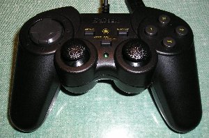
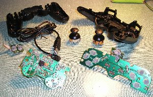
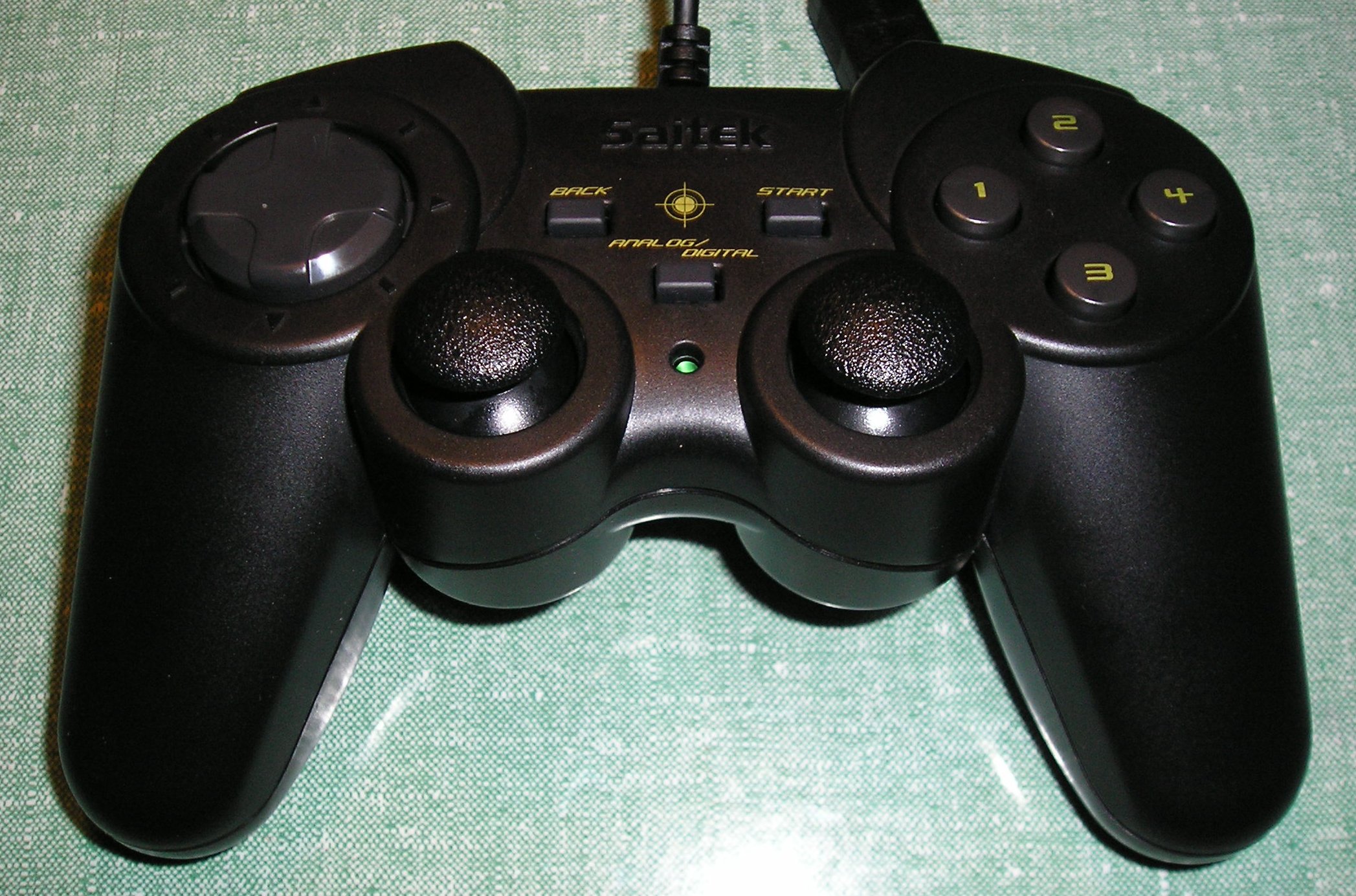
Cheap USB PC game controllers can be picked up for very little money. I got this one for 10 euros. You could probably find a second hand one for even less.
The most useful thing to look is the number of analog controls it will provide. This one has two analog joysticks; each joystick provides two analog controls,
one for each axis, therefore this game pad will provide four analog controls.
The next aspect we can make use of is its buttons. These are also sometimes referred to as digital or binary controls as they offer only two states: 'on' or 'off'.
This device provides sixteen usable buttons: two buttons joypads which offer four buttons each, four buttons on the front face of the controller,
an additional two buttons on the front of the controller labelled 'back and 'start' and finally the two analog joysticks function as buttons when pressed.
|
|
|
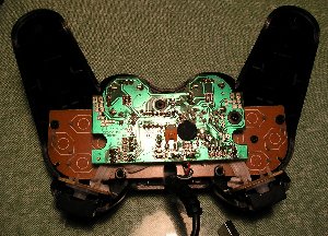
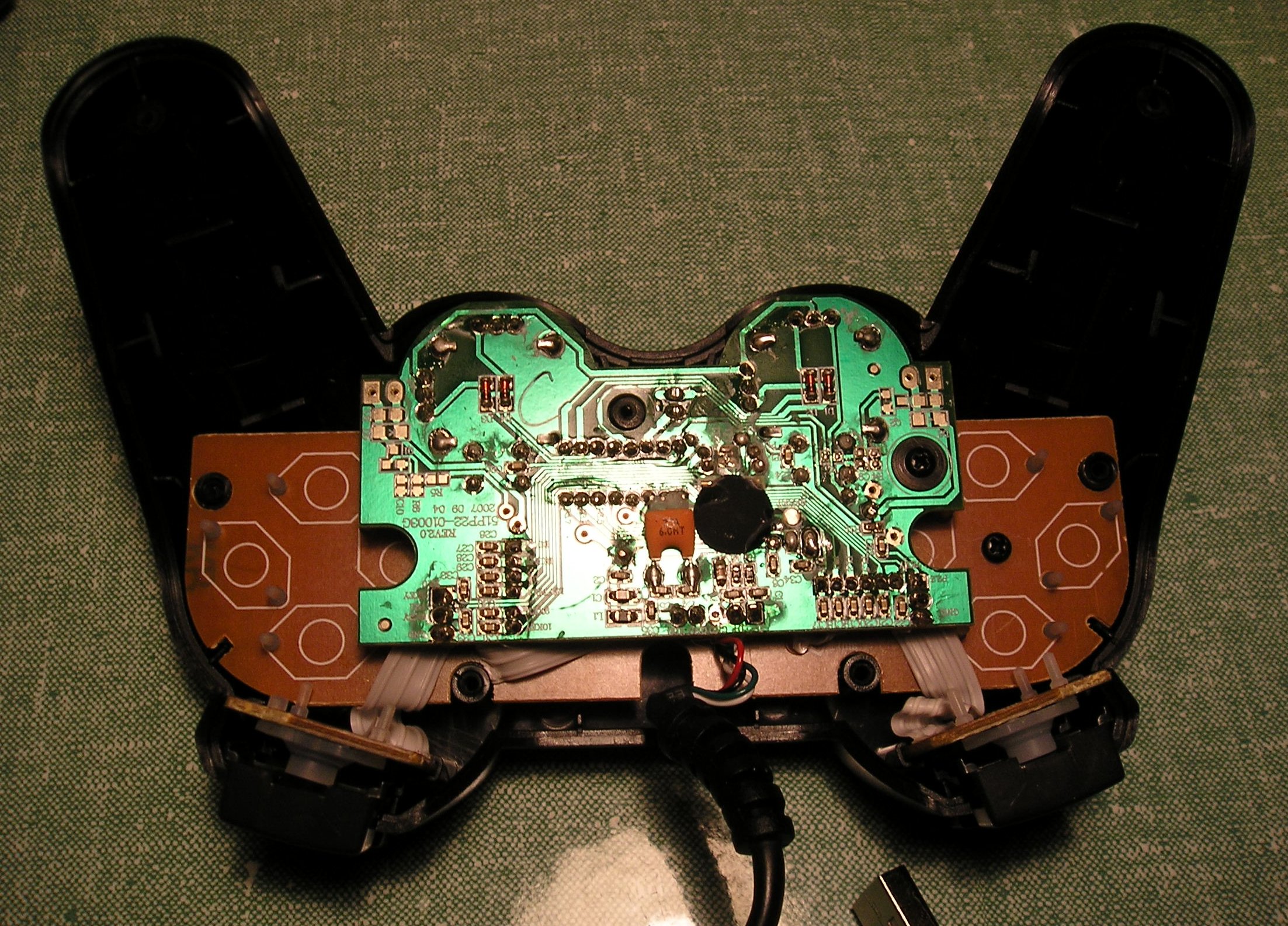
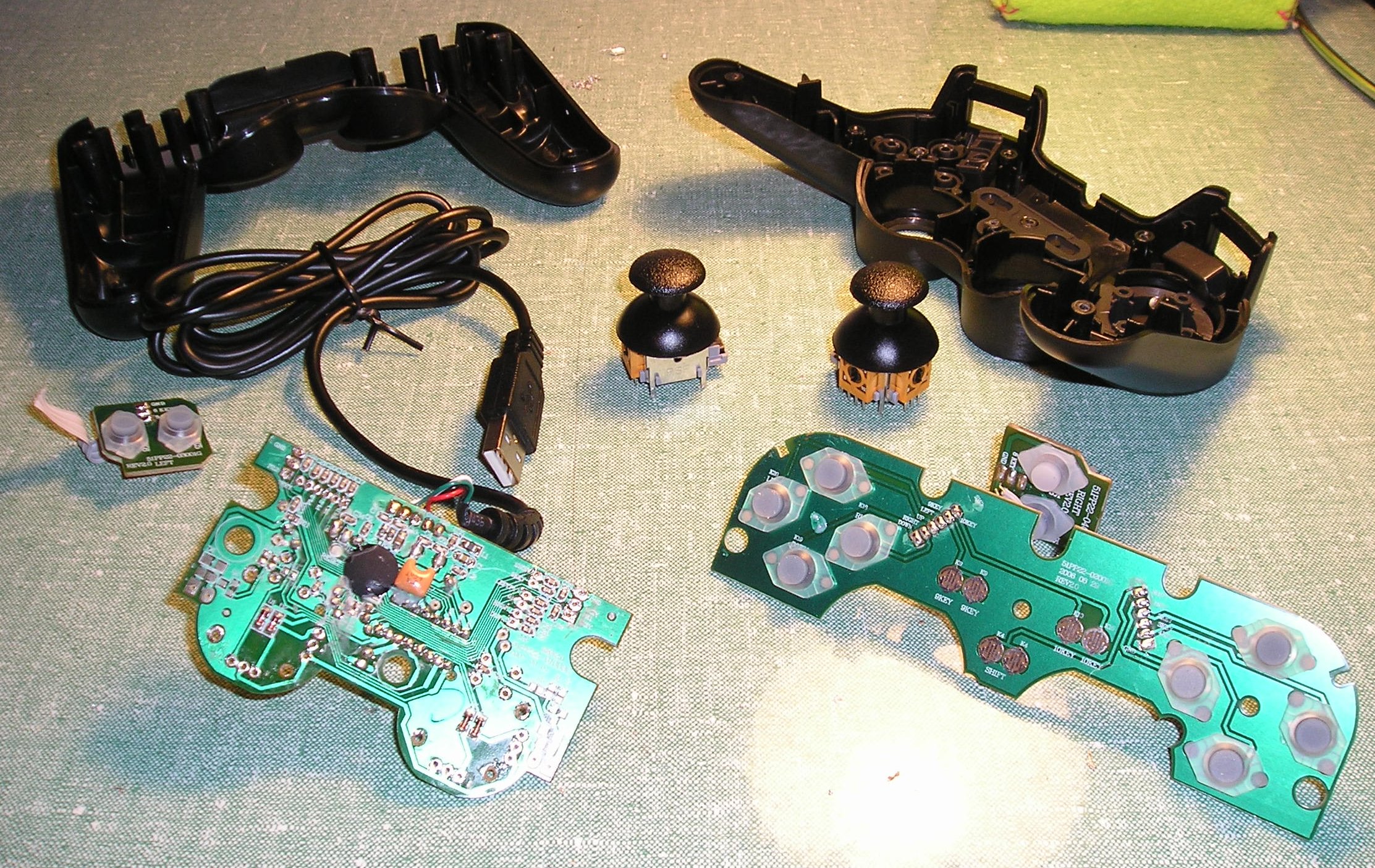
Remove all screws in the underside of the device and with some coaxing, the housing should come apart.
The main circuit board is the green one in the middle, the others are really just for mounting the various switches.
The single integrated circuit (IC) is hidden within the black blob on the right.
The orange item to the left is a capacitor, probably used to smooth the input power supply. All other visible components are tiny surface mount resistors.
There are a couple of diodes on the underside of the board underneath the analog joysticks.
Finally a green LED lights up when the device receives power and is working correctly.
|
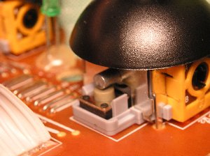
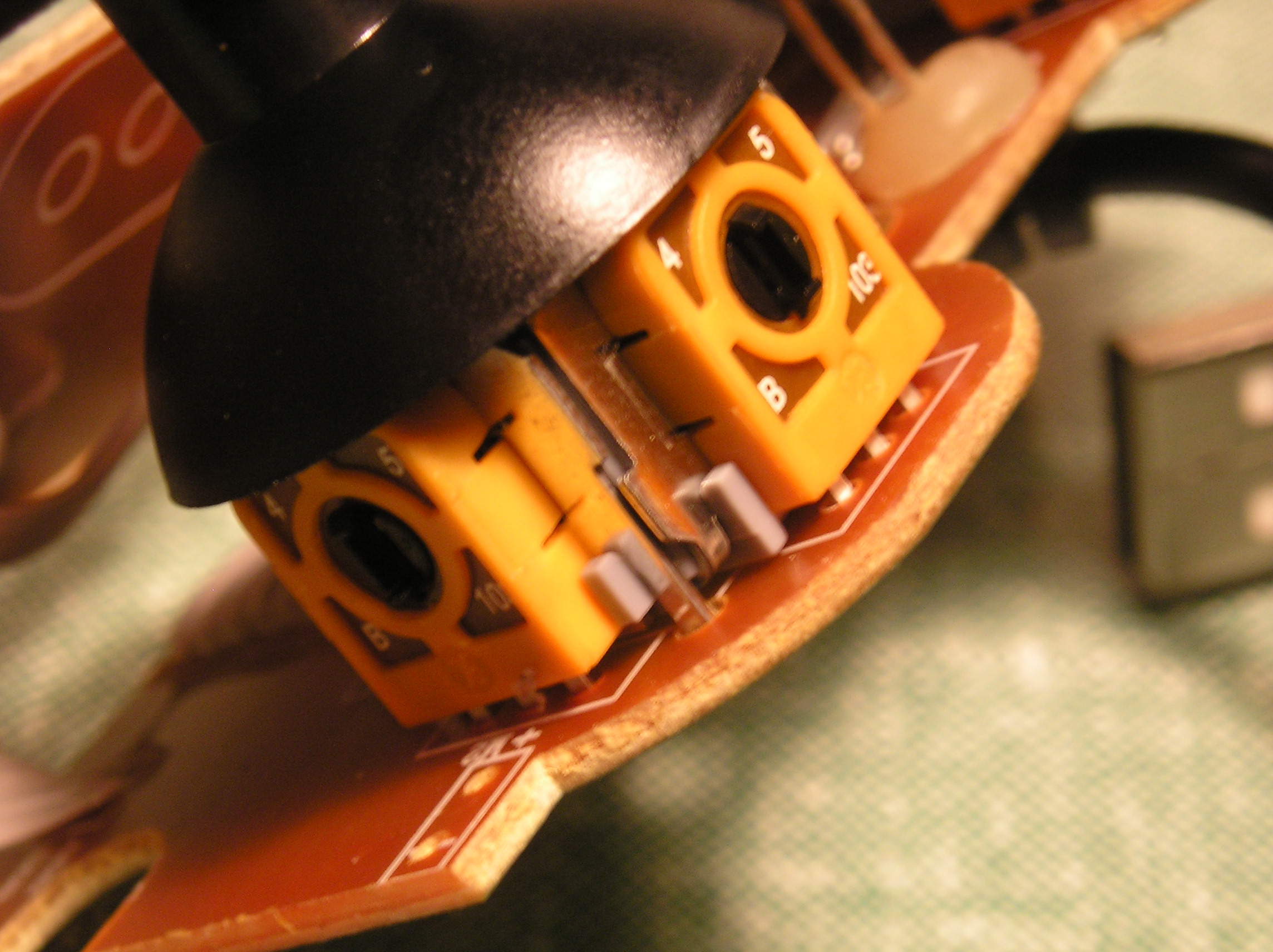
Here is a close up of one of the joysticks.
It is basically comprised of two potentiometers at right angles to each other,
you can just about see the three terminals of each potentiometer leading out from the potentiometer's plastic housing.
The joystick is spring loaded across each axis so that it always returns to its central position.
This means that each potentiometer has an equilibrium position roughly halfway along its travel.
Each time the gamepad is connected and powered up it calibrates each joystick axis by sensing this equilibrium position.
This is done in case the equilibrium position is not mechanically halfway along a potentiometer's
travel or in case one of the potentiometer's resistive qualities has changed on acount of wear and tear or corrosion.
This boot up calibration is something we need to be aware of whenever we connect unconventional controls to replace the joysticks and will be discussed later on.
|

|
|
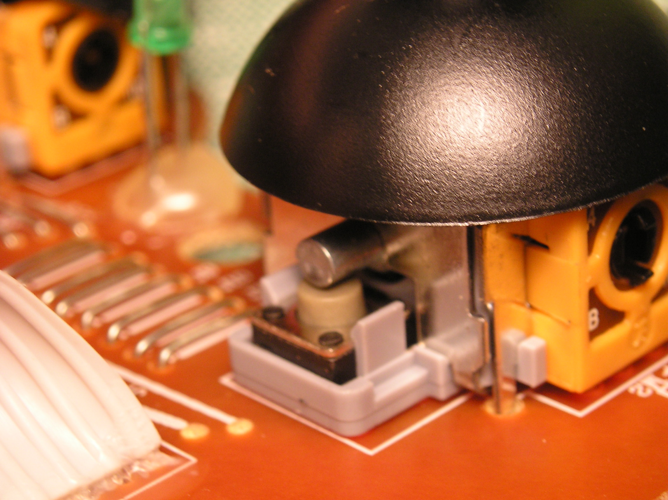
Each joystick unit also functions as a switch when pressed. In this picture you can see the switch in question.
A short metal bar pushes down on the button to activate the switch.
Every button in the gamepad has two terminals. When a button is pressed a closed circuit is made between these terminals.
For each switch one of these terminals is common to all and is referred to as 'ground' (GND).
Bearing this in mind will simplify connecting switch terminals to external devices as
we will only need to bring a ground connection from the gamepad circuit board once.
|
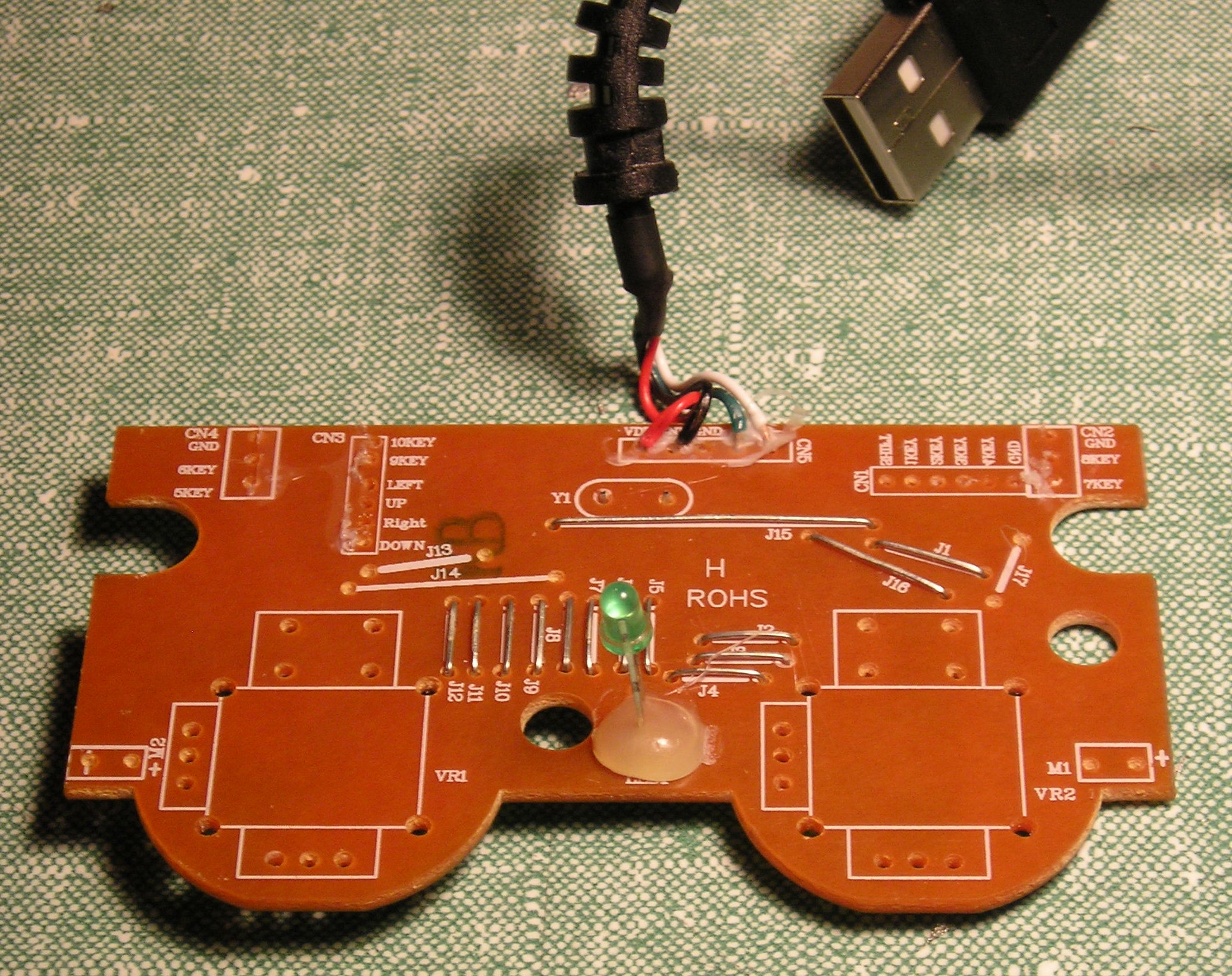
You will need to carefully remove each of the joysticks from the circuit board.
The first stage of this procedure is to remove the solder that binds each terminal to the circuit board.
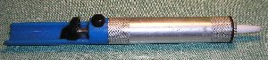
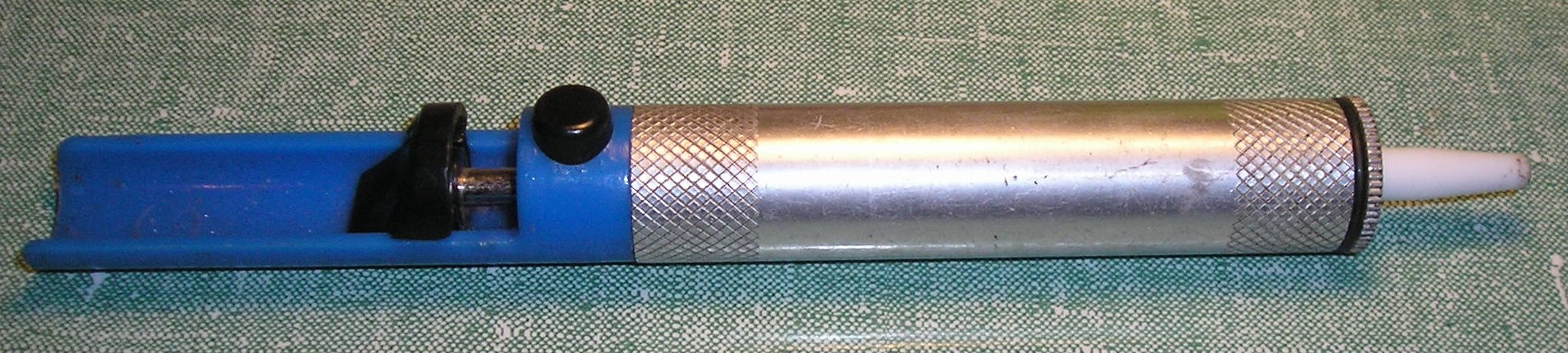
There are many several ways of doing this but probably the cheapest is a de-solder pump like the one shown opposite.
It shouldn't cost more than a few euros/pounds/dollars. Simply melt the solder with a soldering iron and suck the
molten solder into the barrel of the de-solder pump by pressing its button and releasing its spring.
Several attempts may be required to remove all solder from a connection.
Each joystick is also anchored to the board by four metal tabs which are bent around the board.
These will have to be carefully bent straight once the solder has been removed to release the joystick from the board.
Fine nosed pliers might prove useful for this task.
|
|
|
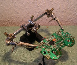
You might find a tool like this useful for holding the board and leaving two hands free for a
soldering iron and the soldering pump.
|
|
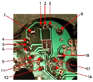
Each joystick is connected to the board in 14 places as indicated in the diagram opposite.
The function of each connectionis outlined below:
1,2,3 Potentiometer Terminals (y-axis)
4,5,6 Potentiometer Terminals (x-axis)
7,8,9,10 Anchoring Tabs (no electronic function)
11,12,13,14 Switch Terminals (only 11 & 12 are used)
|
|
Here one of the joystick mechanisms has been removed revealing the connection points discussed above.
It may require a bit of perseverance to remove the joystick cleanly.
Gentle prising and poking with a narrow flat bladed screwdriver might also help.
Resist the temptation to use force as you run the risk of damaging the board from bending or scraping it.
|
|
|
Once both joysticks have been removed the next step is to remove the ancillary
boards upon which additional switches are mounted.
Use the same technique of first removing excess solder using the solder pump.
Each of the little boards are connected to the main board via it own individual ribbon cable.
Make the disconnection at the main board end as we will want to reuse the terminal on the main board.
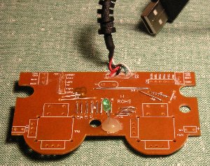
In the picture opposite all ancillary boards and joysticks have been removed.
You should be left with the main board connected to its USB cable.
|
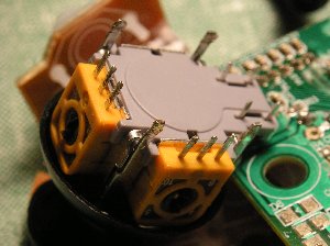
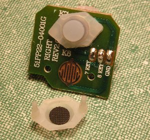
Hold onto the little switches, you might find a use for them later by reinstating them in some other device.
The interlocking lines on the board correspond to the two terminals of the switch.
The black pad on the underside of the switch is conductive rubber.
Pressing the switch causes this black pad to be pressed against the board thereby creating a closed circuit between the two switch terminals.
Note also the written indications on right hand edge of the board and the routes of the connecting tracks.
The '7 KEY' connection goes to the upper switch and the '8 KEY' connection goes to the lower switch.
The 'GND' (ground) connection is common to both switches
|
|
|
|
We are now ready to connect other components and sensors to the various analog and digital inputs of the dismantled gamepad.
However, first some careful consideration of the analog (joystick) inputs is required.
|
It is probably worth investigating what value of potentiometer has used for the joysticks.
Connect a multimeter set tpo measure resistance to the outer terminals of one of the potentiometers (for instance terminals 1 and 3 from the diagram above).
In my gamepad they are 10k (kilo-ohm) potentiometers.
When the joystick is in its equilibrium position the resistance reading between the inner terminal
and either of the outer terminals should be about half of the total resistance, therefore 5k.
So far I have referred to the analog controls as potentiometers as they appear to use three connections with
a central wiper that measures the potential difference between the two extremities of a resistive strip.
However is reality, at least with my device, only two of the three connections for each analog input are used therefore the input
is measuring resistance and the device connected should be referred to as a variable resistor.
Which two terminal points are used can be ascertained either from visual inspection, inspection using a multimeter or as a last resort via trial and error.
|
|

|
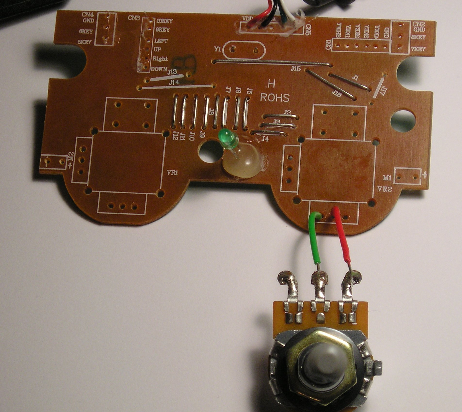
In the picture opposite I have ascertained which two terminals are used by the gamepad for an analog input
and connected them to two terminals of a 10k potentiometer appropriately.
Because the gamepad calibrates each of the analog input when powered up it expects some sort of resistance
to be connected to each of the analog terminals when powered up.
If any of the analog terminals are left unconnected the device will not work at all!
The arrangement shown opposite will not work until appropriate devices are connected to the other three analog controls.
Even once this is done we still have to deal with the fact that when the device is turned on it is assuming that all the analog controls are at their halfway positions.
We could always ensure that rotary potentiometers and sliders are physically at their halfway positions
when plugging the device in but this will quickly become an irritation
and if the connected sensors are light sensors or pressure sensors it will become virtually impossible.
An alternative method of dealing with this problem is shown below.
|
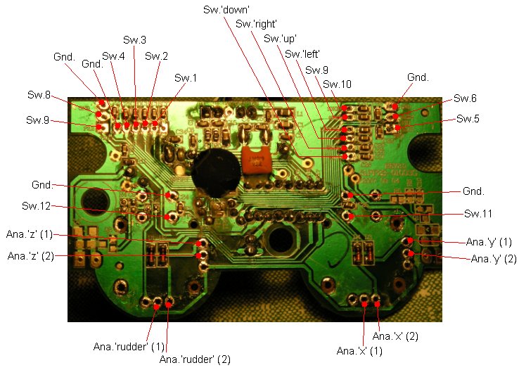
Below is a diagram outlining all the useful connections to the main board.
Remember that all Gnd (ground) connections are common and you only need to bring one Gnd. connection to any external switch interace you build.
The diagram below is only valid for the device I have used.
If you are working from a completely different device you will have to do your own detective work!
Most of the connections are also labelled on the board itself.
|