Low Profile Switch |
You will need:
- Adhesive copper tape
- PVC paper
- Insulation tape
- Piece of wood for base.
- 10k resistor
- Multimeter, scissors, ruler.
|
This is a design for a low profile switch.
There is little or no sense of movement in the switch mechanism as it is pressed and activated therefore it can thought of as a 'touch' switch.
It simply employs two switch contacts made from adhesive copper tape stuck to pieces of plastic sheeting separated by a very thin air gap which is created by an offset created by an insulating tape 'lip'. |
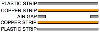 fig. 1
|
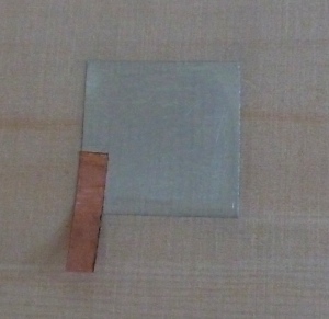 fig. 2
|
Stick a square of copper tape (in this example I have used aluminium tape) onto the base of the switch which in this example is a piece of plywood. There is no strict rule regarding what size this square should be but it will depend on the application. In my example the square is 30 x 30mm which will form a good finger sized switch. The switch relies on the springiness of the plastic sheet to maintain the air gap when the switch is released therefore there will probably be a maximum size this can be made beyond which the switch will be in danger of sagging and making false contact. Attach a short tab onto one corner of the square. It is important that you use adhesive copper tape with conductive adhesive. Fold this tab over onto itself to create a sturdy tab to which connections can be made later. |
|
Form an outlined square of insulating tape around the piece of copper or aluminium tape. The insulating tape strip should overlap both the metal/aluminium tape square and the wood. This insulating tape 'lip' will prevent the upper and lower switch contacts from touching by maintaining a thin air-gap when the switch is released. |
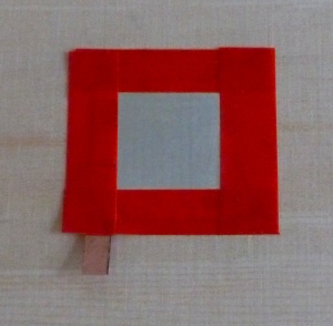 fig. 3
|
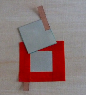 fig. 4
|
Form the upper part of the switch by sticking another square of copper or aluminium tape onto a piece of plastic/PVC paper. Attach another small tab of copper tape that will be used for making connections to the other contact of the switch. |
|
This square should be slightly larger than the exposed copper tape that forms the lower contact so that it rests on the insulating tape square. |
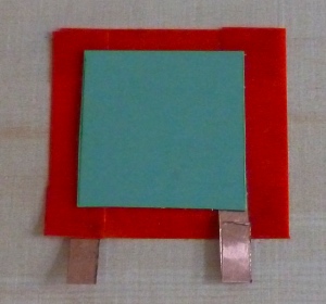
fig. 5 |
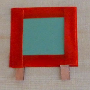 fig. 6
|
Affix the upper part of the switch using insulation tape or glue. If using glue take care not to get glue on the conductor. |
|
Connect one of the tabs of the sensor to 5 volts (5v) and the other to an analog or digital input of your Arduino (or equivalent). Connect a resistor between the same analog or digital input and ground (see fig. 7). Typically this resistor should be around 10 k.ohms. This resistor is referred to as a 'pull-down' resistor as it pulls the sensor input down to ground potential when the switch is released. |
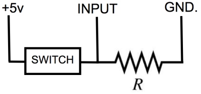 fig. 7
|
|
The switch has just two states, on or off, interpretted by a digital input as high or low and by an analog input as maximum (1024 for an 8 bit input or 127 for MIDI) or minimum (0). |
|
A sequence of switches with no interruption can be formed by creating the upper part of the switch with a single piece of plastic. The side of the switch that will connect to 5 volts can be made using a single continuous conductor for convenience - it isn't necessary to make multiple connections to 5v. |