This design for a ribbon controller makes use of the electrically conductive characteristic of pencil graphite.
Darker pencil lead offers lower resistance and in this project a 6B to 9B pencil is recommended.
You may need to visit an art supplies shop to find one of these.
Pencils this dark tend to be rather crumbly so sharpening them become more of a 'negotiation'.
Make sure you use a good quality metal sharpener and don't bother trying to achieve a needle sharp tip which won't be necessary anyway.
A couple of millimetres of exposed lead will be sufficient.
Additional materials required are outlined below.
fig. 1
fig. 2
A good solid flat board is required upon which to build the ribbon controller. 12mm plywood should be adequate.
There is a fair degree of flexibility with how long you can make your ribbon controller.
This is largely because the design is implemented as a potentiometer (with three electrical connections being made from the sensor)
rather than as a variable resistor with two electrical connections. It can be as short as a few centimetres up to more than a metre.
The board I am using in this example is 30 x 6cm.
Bare in mind that longer ribbon controllers may also need to be wider.
Longer graphite strips will also depend more upon darker, lower resistance graphite so that 9B pencils might become essential.
We will draw a long trapezium onto a piece of paper to create something equivalent to the carbon strip in a fader.
The 'wiper' part of the fader is created using a guitar string suspended just above the graphite strip.
I recommend fairly light gauge electric guitar strings as being easier to work with.
0.01" (0.245mm) strings which are normally used for the high E string will work well.
fig. 3
fig. 4
The guitar string will be suspended above the graphite string using a 'bridge' 'tailpiece' design at either end
inspired by that employed by most string instruments.
The bridges and tailpieces will be formed using short screws.
The screws for the bridges should be straight slotted and 10-12mm in length (fig. 4)
The heads of the screws used for the tail pieces need to have flat bases (fig. 5), not conical like the screws in fig. 4.
They can be either straight or cross-headed although you will find cross-headed screws to be much more common.
Alternatively a small washer could be used to create a flat base. Again the screws should be 10-12mm long.
If you use longer screws they will just come through the bottom of the board.
fig. 5
fig. 6
An alternative to using guitar strings is to use conductive thread (fig. 6) although I haven't thoroughly tested this yet.
Conductive thread in not quite as conductive as a guitar string but this is unlikely to be an issue in this circumstance.
Some conductive silver paint (fig. 7) is helpful but not essential in improving the connection between the copper tape and the graphite strip.
This is sold in small jars from electronics shops.
In addition to the items discussed above you will need some adhesive copper tape (with conductive adhesive), a piece of paper, spray mount, some PVC paper (or similar) some insulation tape and a resistor.
Tools required are pliers (in fact having two sets of pliers might prove helpful), a drill, wire cutters, a ruler, scissors and screwdrivers.
As always a multimeter will prove useful for testing and troubleshooting.
fig. 7
fig. 8
The first step in construction is to draw a long trapezium on a piece of paper.
I have found that a trapezium rather than an oblong produces a more even change in sensor data.
The longer end of the trapezium should be about twice as wide as the shorter end.
In my example the longer end is 40mm and and shorter end is 20mm. The length of the trapezium is 250mm.
Take care to colour the shape in solidly. Affix the paper to the base board using spray mount.
You will notice that a few centimetres have been left at either end of the board to allow space for the bridges and tailpieces.
Stick strips of adhesive copper tape onto either end of the graphite strip.
Small blobs of conductive paint can be placed between the copper tape and the graphite strip to improve conductance between the two.
These blobs should not be placed right in the middle above where the string will lie.
fig. 9
fig. 10
Stick some insulation tape over the copper tape added in the previous step. Now the bridge screws and tailpiece screws can be added.
Affix another piece of copper tape over the hole where one of the bridge screws will go, it doesn't matter which one.
You will need at least a centimetre gap between these and make sure the bridge screw doesn't pierce the the copper tape added previously and now under the insulation tape.
The tailpiece screws should be offset slightly so that the string will run straight around the shaft of the screw from the bridge screw.
This can be seen more clearly in some of the later diagrams and pictures.
The guitar string should be wound clockwise around the tailpiece screw so that tightening the screw will tighten the string.
For attaching the string, two sets of pliers might prove useful (as will the assistance of a friend!).
Fig. 11 should clarify where the various elements of the ribbon controller design go and also where connections will lead to.
fig. 11
Figs. 12 - 14 show details of the bridge-tailpiece construction.
fig. 12
fig. 13
fig. 14
fig. 15
A channel should be created using strips of insulation tape (or glued thin strips of cardboard or plastic) on either side of the guitar string.
Two layers of insulation tape should be sufficient. Creating this channel will prevent the upper plastic sheet layer of the ribbon controller
from pulling the guitar string down onto the graphite strip.
The close up of the guitar string and surrounding channel in fig. 16 should illustrate the height of the string above the graphite strip and the
height of the sides of the channel formed using insulation tape.
fig. 16
fig. 17
A strip of acetate that is slightly wider and longer than the channel is affixed on top of the guitar string using insulation tape.
Other exposed contacts are covered using insulation tape.
The wide end of the graphite trapezium will connect to ground, the narrow end to +5 volts and the guitar string connects to an analog input (fig. 11).
A resistor should be connected between the analog input and groung to prevent random values being read when the ribbon is not being touched.
A video demonstration illustrates that the ribbon sensor built in this accesses almost the complete range of possible values for an analog sensor.
For the ribbon controller to access the maximum and minimum values of the analog input it is essential that the copper tape at either end of the graphite strip makes a good electrical connection.
The conductive paint blobs help to achieve this. You could also just expose a little bit of the copper tape
but this could result in a sudden jump to the maximum or minimum value as the guitar string make contact with the copper tape.
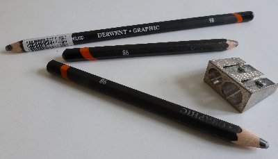 fig. 1
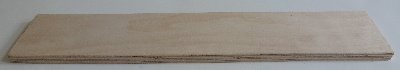 fig. 2
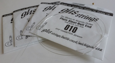 fig. 3
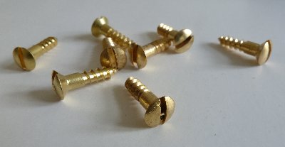 fig. 4
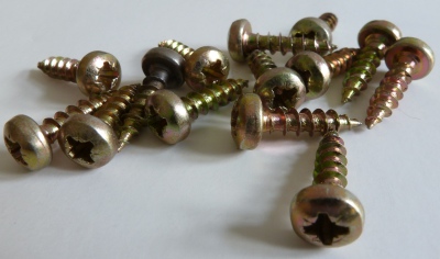 fig. 5
 fig. 6
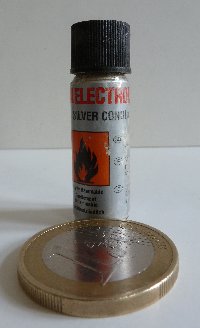 fig. 7
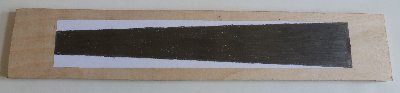 fig. 8
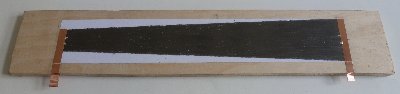 fig. 9
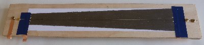 fig. 10
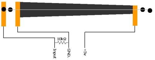 fig. 11
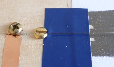 fig. 12
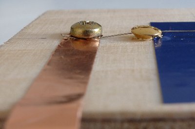 fig. 13
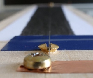 fig. 14
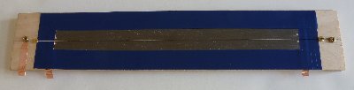 fig. 15
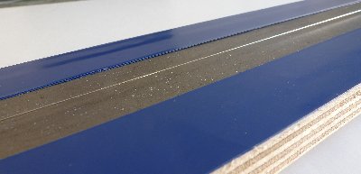 fig. 16
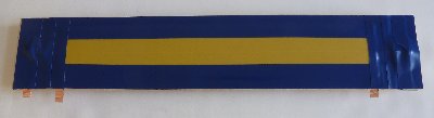 fig. 17