DIY Sensors Workshop |
1. Interfacing Options
We looked at a number of options for interfacing sensors with a computer.
A popular option is the Arduino:
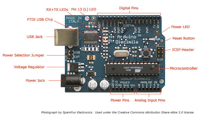
The Arduino offers the advantage that a lot of people are using it so it is usually quite easy to get help or information via the internet.
The main website for the Arduino is: http://www.arduino.cc/.
The Arduino can also be programmed to behave in many different ways. It has 6 analog pins (continuously varying controls like a light sensor)
and 14 digital pins (on off switches for example. All of these pins can be either inputs or ouputs meaning that as well as transducing information
from a sensor a pin could be used to, for example, turn on a light, activate a motor or solinoid. Its analog pins offer a high resolution (10 bit)
which means 1024 different values which is superior to the 7 bit / 128 values of a MIDI continuous controller. A disadvantage of the Arduino is that
communication with software is not as simple as with MIDI although if you are using software for which there are already implemented interpretters such as
MaxMSP or PD then this won't be a problem. If you need to convert the Arduino's data to MIDI you could try
Junxion.
If you just want to use the Arduino as a sensor interface you will need to program it with a so-called Firmata.
This is a simple procedure which is carried out from the Arduino environment program, downloadable from the Arduino website.
Another option we looked at for the input of analog / continuous sensors was the Doepfer Pocket Electronic The Pocket Electronic has 16 analog inputs and outputs data as MIDI continuous control messages so it is easy to interface with a wide variety of software and hardware.
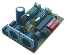
 The Doepfer CTM64 offers 64 digital inputs (on/off switches) and outputs each switch as either a
MIDI note on/off message of as a MIDI continuous control message (on=127,off=0).
The Doepfer CTM64 offers 64 digital inputs (on/off switches) and outputs each switch as either a
MIDI note on/off message of as a MIDI continuous control message (on=127,off=0).
 An obvious implementation would be to connect the switch inputs to the keys of a keyboard but any number of more imaginative implementations are possible.
Another option we looked at for the input of analog / continuous sensors was the Doepfer Pocket Electronic The Pocket Electronic has 16 analog inputs and outputs data as MIDI continuous control messages so it is easy to interface with a wide variety of software and hardware.
2. Sensors
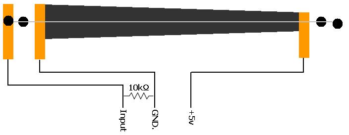
We considered a number of sensors during the workshop. We built a ribbon controller.
Below is a diagram of how it was constructed and how it could be connected to a sensor interface (either an Arduino or a Doepfer Pocket Electronic).
Note the 10 kilo-ohm (10,000 ohm) resistor between the input and ground connections to prevent random values being generated when the ribbon is not being touched.
|
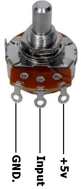
If you simply wish to connect a potentiometer to a sensor input here is how: A linear potentiometer with a value of 10 kilo-ohm is normally a good choice with sensor boards although as this is a potentiometer (3 connections) and not a variable resistor (2 connections) the precise value value shouldn't matter too much. If you were to use an extremely high value pot, say 10 megaohms then the sensor input might struggle to hold a stable value. If you used an extremely low value, say 10 ohms then it may not be able to reach to minumum and maximum values for the sensor input. No additional resisitor is required this time as there is always some sort of connection to 'ground' within the potentiometer. If the control is turned fully counter-clockwise then there will be close to zero resistance between the input and ground (GND.) and maximum resistance (e.g. 10k) between input and +5v. The input will receive 0v and the sensor will give a minimum value, zero for MIDI. If the control is turned fully clockwise then there will be maximum resistance between input and ground and minimum resistance between input and +5v, the input will receive 5v and therefore a maximum sensor reading which in the case of MIDI will be 127. If the control is exactly in the middle then there will be equal resistance between input and ground and between input and +5v. If we are using a 10k linear potentiometer then this resistance will be equally divided, there will be 5k between input and ground and 5k between input and 5v. |
|
|
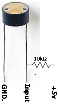
Light dependent resistors (LDRs) are cheap and useful sensors. Opposite is shown how to connect one to a sensor input.
Experiment with different types. Larger ones (with more wavey lines on them) will tend to provide a lower minimum resistance and therefore output a wider range of values. You can expect to pay the equivalent of 1 euro or more for a decent one. Connecting two or more smaller LDRs can provide equivalent behaviour to a single larger one. As this is a varible resistor (2 connections) as opposed to a potentiometer (3 connections) we need to connect a 10k static resistor between the input and 5v. You can experiment with different values for this static resistor, perhaps within the range 5 - 100k. Depending on the LDR you are using you will get a different range of output values but the scope of the range will probably not change. It is unlikely that an LDR will yield a full range of sensor values but obviously better lighting conditions will increase the range possible. |
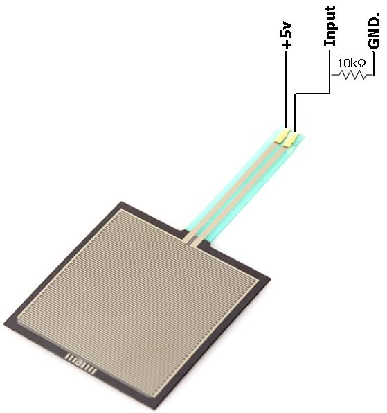
| We looked at how to make a home-made pressure sensor from copper tape and anti-static packing foam but if you're prepared to pay (at least 10 euro) you can get a professional one (referred to as a Force Sensitive Resistor / FSR and pictured opposite) which will have a lower profile and possibly be more sensitive. Again this device is a variable resistor as opposed to a potentiometer. This time we connect the sensor beween the input and +5v and the 10k resistor between input and ground. The reason that this is done the opposite way around than for the LDR is that whilst resistance increases as a hand is drawn over the LDR, resistance decreases as pressure is applied to the pressure sensor. It would seem to make more sense for sensor value to increase as an LDR is covered or as an FSR is pressed. The connection arrangement is the same for the home made version. |
|
|
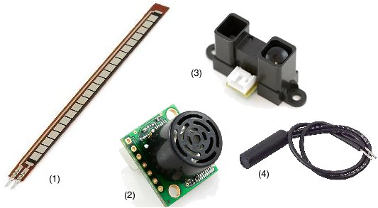
Other sensors worth investigating are flex (bend) sensors (1) which could, for example, be installed within the fingers of gloves to sense the bending of fingers, ultrasonic distance sensors (2) which measure the proximity of an object in front of them up to a range of several metres, infrared proximity sensors (3), which again measure distance of obstructing object but work best over a shorter distance and magnetic reed switches (4) which activate a switch when a magnet is brought close to them. |
3. Some Basic Electronics
It isn't necessary to become a qualified electrical engineer to do interesting things with sensors but a little basic knowledge will help.
Three basic aspects of electricity we should be aware of are voltage, current and resistance.
It is useful to use the analogy of water flowing through a plumbing system in order to understand these definitions.
Voltage is value relative between two points in a circuit that defines the potential for electricity to flow between those two points, this is sometimes referred to as 'potential difference'. That 'potential' is fulfilled when some sort of circuit is completed between the two points. In order for electricity to flow there has to be a voltage difference within the circuit. A reference point known as 'ground' potential is defined above (and below) which all other voltages are measured. Voltage is measured in 'volts' with a 'voltmeter' or the DC voltage setting on a multimeter. Using our analogy, voltage can be thought of as the height difference between a water tank and a tap that permits water to flow - a greater height difference creates the potential for more forceful water flow.
Current is the potential volume of electricity that can flow and using the water analogy is the volume of water available to flow and more precisely the rate at which the tanks is refilled. Normally we need concern ourselves less with current, it mainly becomes an issue when a power source is incapable of supplying sufficient current that a circuit demands. Current is measured in 'amps' using an 'ammeter'. This must be done in series within the circuit so a circuit will have to be broken in order to make this measurement.
Resistance is a measure of the inability of a material to conduct electricity. A material that conducts extremely easily is referred to as a conductor. A material than almost completely resists conduction is referred to as an insulator. Anything in between is a resistor. Resistance is measured in ohms using a resistance meter, a function found on all multimeters. Common measurements are very large so instead the 'kilo-ohm' becomes the most used unit of measurement. 1000 ohms = 1 kilo-ohm. Kilo-ohm is frequently abbreviated to just 'k'. In our water analogy resistance is therefore the resistance of the plumbing system to the flow of water - more precisely, the gauge or thickness of the pipes.
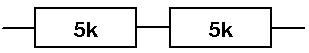
If resistors are connected in series the resultant resistance is simply the sum of all the resistors:
R_total = R1 + R2
In the example below the total resistance would be 10 kilo-ohms.
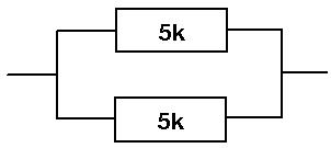
If resistors are connected in parallel the formula used is as follows:
1/R_total = 1/R1 + 1/R2
Using this formula the total resistance in the example shown below would be 2.5 kilo-ohms.
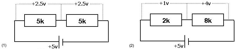
In (2) changing the values of the resistors changes proportionally how the voltage is divided.
This is the principle behind how all of our passive (unpowered) analog sensors work.
It is useful to use the analogy of water flowing through a plumbing system in order to understand these definitions.
Voltage is value relative between two points in a circuit that defines the potential for electricity to flow between those two points, this is sometimes referred to as 'potential difference'. That 'potential' is fulfilled when some sort of circuit is completed between the two points. In order for electricity to flow there has to be a voltage difference within the circuit. A reference point known as 'ground' potential is defined above (and below) which all other voltages are measured. Voltage is measured in 'volts' with a 'voltmeter' or the DC voltage setting on a multimeter. Using our analogy, voltage can be thought of as the height difference between a water tank and a tap that permits water to flow - a greater height difference creates the potential for more forceful water flow.
Current is the potential volume of electricity that can flow and using the water analogy is the volume of water available to flow and more precisely the rate at which the tanks is refilled. Normally we need concern ourselves less with current, it mainly becomes an issue when a power source is incapable of supplying sufficient current that a circuit demands. Current is measured in 'amps' using an 'ammeter'. This must be done in series within the circuit so a circuit will have to be broken in order to make this measurement.
Resistance is a measure of the inability of a material to conduct electricity. A material that conducts extremely easily is referred to as a conductor. A material than almost completely resists conduction is referred to as an insulator. Anything in between is a resistor. Resistance is measured in ohms using a resistance meter, a function found on all multimeters. Common measurements are very large so instead the 'kilo-ohm' becomes the most used unit of measurement. 1000 ohms = 1 kilo-ohm. Kilo-ohm is frequently abbreviated to just 'k'. In our water analogy resistance is therefore the resistance of the plumbing system to the flow of water - more precisely, the gauge or thickness of the pipes.
Calculating Combined Resistance
Often it is useful to calculate a resistance created by a combination of more than 1 resistor. There are two ways in which resistors can be connected within a circuit: in series or in parallel and we use a different formula for each method.If resistors are connected in series the resultant resistance is simply the sum of all the resistors:
R_total = R1 + R2
In the example below the total resistance would be 10 kilo-ohms.
If resistors are connected in parallel the formula used is as follows:
1/R_total = 1/R1 + 1/R2
Using this formula the total resistance in the example shown below would be 2.5 kilo-ohms.
The Voltage Divider
If we consider the two resistors in parallel example and consider a voltage of 5 volts being applied across this circuit then the resistors effectively divide the total voltage in two. The voltage between the point between the two resistors and either of the two end points will be 2.5 volts as shown in (1).In (2) changing the values of the resistors changes proportionally how the voltage is divided.
This is the principle behind how all of our passive (unpowered) analog sensors work.
4. More on the Doepfer CTM64
The Doepfer CTM 64 provides an interface for 64 switches (as well as pitch bend, modulation wheel (CC#1), volume (CC#7) and aftertouch continuous controllers).
These switches can either output MIDI notes ('note on' when contact is made, 'note off' when contact is removed) or
two states of a continuous controller (MIDI value 127 when contact is made, MIDI value zero when contact is removed.
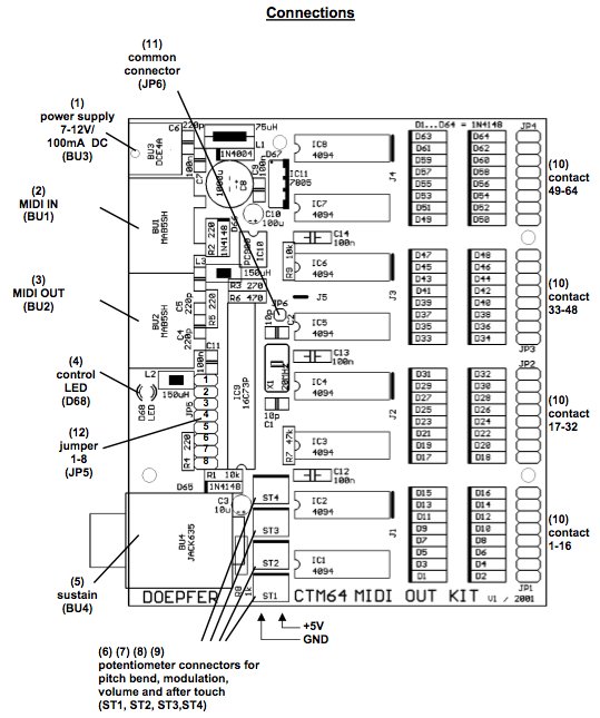
Each switch consists of two connections which when connected turn on that switch and when disconnected turn off that switch.
One of these contacts is unique to each switch whilst the other is common to all switches - this is a common approach to switch matrix design.
In the diagram above the common connection is labelled (11) jp6, connection to the unique contact for each switch is made via ribbon cables and the connectors labelled (10) in the schematic above.
The CTM64 is powered by a DC power adapter with voltage in the range 6-12v. This could be replaced by a 9v battery for mobile projects.
5. More on the Doepfer Pocket Electronics
The Doepfer Pocket Electronic provides 16 analog sensor inputs. Sensor data is output as MIDI continuous controller data.
Continuous Controller numbers and MIDI channel number for each input can be programmed using tiny switches on the board itself
or better still using its editing software.
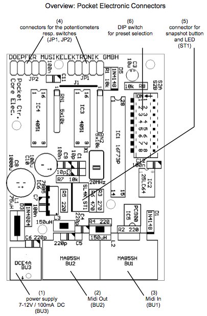
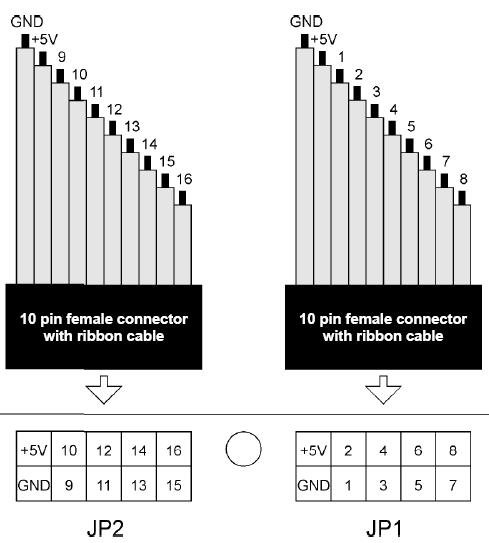 Connection to the PE board is made via two 10-way ribbon cables.
These cables are normally included with the PE package but you can obtain them separately - ask for 2mm gauge 10-way IDC cable and 10-way (2 rows of 5) IDC connectors. Normally one of the cables in the ribbon is coloured differently to facilitate identification from one end to the other. It's probably best to match this differently coloured strand to the 'GND' connection. You can find the 'GND' and '+5v' connections used by all the analog sensors discussed in section 2. These connections on JP1 and JP2 are essentially the same and are included on each ribbon connection for our convenience, you can use both or either depending on which is most convenient for the particular project. The numbered connections are the sensor inputs, eight on each ribbon cable. If sensor inputs are left unconnected they mey generate random values - this may or may not be a problem in the final project but it is good practice to connect unused inputs to ground. We will encounter and deal with this issue with the Arduino in the same way. One way to deal with this issue is to employ switched jack sockets as the sensor input connection which connect inputs to ground when nothing is plugged in (see below).
The PE requires a DC power supply to operate. It is relatively unfussy about the voltage and will operate between 6 and 12 volts. Current draw is quite low so battery operation (perhaps using a 9v battery) is possible, simple fashion a battery clip that connects to the DC socket.
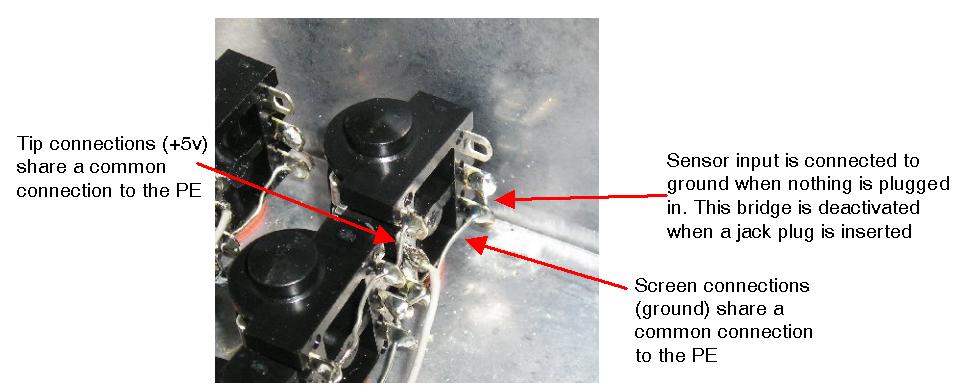
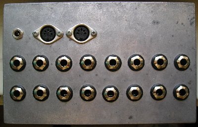
You could build the PE into a sensor box for the convenience of plugging sensors in and out as shown below:
In this design I have chosen the convention of using stereo 1/4" jack plugs and sockets for sensors with the 'tip' connection corresponding
to +5v, the 'ring' corresponding to the sensor input and the 'screen' connection corresponding to 'ground'.
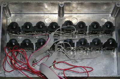
In the close-up image below you can observe how all tip connectors (+5v) share a common connection. The same is true for the screen (ground) connections. You can also observe how sensor inputs are connected to ground whenever that socket is not in use.
These cables are normally included with the PE package but you can obtain them separately - ask for 2mm gauge 10-way IDC cable and 10-way (2 rows of 5) IDC connectors. Normally one of the cables in the ribbon is coloured differently to facilitate identification from one end to the other. It's probably best to match this differently coloured strand to the 'GND' connection. You can find the 'GND' and '+5v' connections used by all the analog sensors discussed in section 2. These connections on JP1 and JP2 are essentially the same and are included on each ribbon connection for our convenience, you can use both or either depending on which is most convenient for the particular project. The numbered connections are the sensor inputs, eight on each ribbon cable. If sensor inputs are left unconnected they mey generate random values - this may or may not be a problem in the final project but it is good practice to connect unused inputs to ground. We will encounter and deal with this issue with the Arduino in the same way. One way to deal with this issue is to employ switched jack sockets as the sensor input connection which connect inputs to ground when nothing is plugged in (see below).
The PE requires a DC power supply to operate. It is relatively unfussy about the voltage and will operate between 6 and 12 volts. Current draw is quite low so battery operation (perhaps using a 9v battery) is possible, simple fashion a battery clip that connects to the DC socket.
You could build the PE into a sensor box for the convenience of plugging sensors in and out as shown below:
|
|
In the close-up image below you can observe how all tip connectors (+5v) share a common connection. The same is true for the screen (ground) connections. You can also observe how sensor inputs are connected to ground whenever that socket is not in use.
6. More on the Arduino
A number of variations of the Arduino are available some larger some smaller.
There are even Arduino clones - copies made by other companies which are sometimes a little bit cheaper.
The most most common Arduino and the best one to start with is the 'Uno' (formerly called the 'Diecimila')
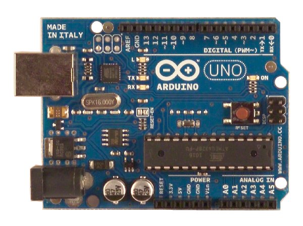 In the image above image you can see the six analog connections (labelled A0 - A5) and the 14 digital connections (labelled digital 0 - 13).
You can also find the 5v connection and several GND connections (you can use either or all of these, they are essentially the same connection).
In the image above image you can see the six analog connections (labelled A0 - A5) and the 14 digital connections (labelled digital 0 - 13).
You can also find the 5v connection and several GND connections (you can use either or all of these, they are essentially the same connection).
Analog sensor connections are made using the +5v, GND and analog input connections (A0 - A5) using the sensor connection schematics given in section 2.
Digital switch connections are made by connecting the switch between the digital connection (0 - 13) and GND.
What makes this Arduino great for prototyping is that connections are made to the board by pushing bared jumper wires or component legs straight into the connection sockets - no soldering is required. Consequently however it is less easy to design a solid finished project, the Arduino 'Nano' or 'Pro' might be more suitable for this.
Remember that the Arduino does not output MIDI. It will first need to be programmed with what is called a 'Firmata' (comes included with the downloadable Arduino environment) - a programme that facilitates meaningful communication between the Arduinos inputs (or outputs) and a variety of software. The software you choose will have to have the facility to work with an Arduino.
7. Useful Tools
Some tools and equipement you may need...
Soldering iron
Solder
Multimeter
Wire strippers
Wire cutters
Pliers
Helping hands
Soldering iron
Solder
Multimeter
Wire strippers
Wire cutters
Pliers
Helping hands
8. Links
'How to' on hacking a gamepad
Arduino website
Doepfer website
Farnell global electronics components distributor
Sparkfun (US) online shop specializing in Arduino and sensor related merchandise
Lipoly (German) online shop for electronics related components and gadgets
Cool Components UK based online shop for Arduino and sensor related merchandise